Environmentally Connected Helium Objects
index
description
technical information
simulation )))
references _
ECHO is customized to specific sites. A computer simulation is carried out to calculate the optimum distance between each blimp and the ratio which the speed must be scaled to. - - - - - - - - - - - - - - - - - - - - - - - - - - - - - - - - - - - - - - - - - - - - - - - - - - - - - - - - - - - - - |
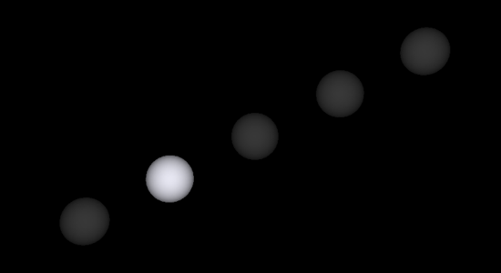
| The current simulation model is implemented with the C++ language, using openGL for the visualization of the spheres. The simulation will specifically aid in determining the proper delay time between illuminations of the spheres, as well as the coefficients for effective mapping from the sound input amplitude to light intensity. The coefficient for attenuation of the signal as it propagates must also be determined based on the rate at which sound waves attenuate in air. These scaling coefficients must be obtained because the speed of sound is slightly too fast for practical visualization in light, and the amplitude of a sound wave is much smaller than the voltage level required for visible light intensity. The following image is a screen shot of the simulation program:
The Echo Phenomenon - - - - - - - - - - - - - - - - - - - - - - - - - - - - - - - - - - - - - - - - - - - - - - - - - - - - - - - - - - - - - Modeling an Echo The parameters that are relevant to the ECHO simulation are the value of the delay line in milliseconds and the delay mix value, which is the coefficient of attenuation as the signal propagates. Each module in the ECHO simulation consists of a basic delay unit and an algorithm that controls the rate at which the peak level of light intensity is reached. The delay portion of the simulation can then be simplified to a loop which sends the input signal through the basic delay unit the correct number of times, corresponding to two times the number of modules in the specific ECHO installation. - - - - - - - - - - - - - - - - - - - - - - - - - - - - - - - - - - - - - - - - - - - - - - - - - - - - - - - - - - - - - Example Simulation Results Sample Scenario: 100m / (340m/s) = .3 seconds --> time required for propagation of whole distance = .6 s Takes .03 seconds to get to first module The time delay and number of modules is then input into the simulation and an animation displays how the propagation will look. The user then scales the time delay up until the visualization of the echo is perceived most clearly. For this simulation the program output indicates that the best time delay is 0.2 seconds between each module. Thus, the scaling factor for this simulation is (0.2/0.03) = 6.67. This means that the visual echo will actually be traveling 6.67 times slower than the actual acoustic wave would travel. The other parameters that must be determined are the rate at which the peak intensity level is reached, and the coefficient of signal attenuation for each module. |
| - - - - - - - - - - - - - - - - - - - - - - - - - - - - - - - - - - - - - - - - - - - - - - - - - - - - - - - - - - - - - |
Mariano Mora -Composer- + Matt Stabile -EE- + Andres Burbano -Artist- |
